If You Need a Portable NVIS Antenna for 40 m, this Homemade Linear-loaded Dipole Can Meet Your Needs.
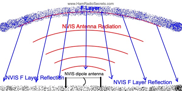
A horizontal half-wave dipole becomes a NVIS antenna when it is installed at less than 1/4 wavelength above ground. The antenna, described herein, is only about one meter (3-4 feet) above ground. It is intended for field work.
Its Near-Vertical Incidence Skywave is reflected back toward earth by the 'F' layer of the ionosphere to cover an area roughly 150 to 200 km (100-125 miles) around the antenna.
At heights less than 1/4 λ, the ground begins to act as a "dull", inefficient reflector. The RF energy, radiated by the dipole, is both directed upward and absorbed by the earth.
The lower the dipole, the more RF energy gets absorbed by the earth, and the less energy gets radiated upward.
The improved S/N ratio of a low-slung NVIS dipole compensates for losses in radiated and captured RF energy.
The vertical gain of a dipole rapidly decreases at heights less than 0.1 λ (3 dB loss at 0.05 λ) above ground level.
But, fortunately, the NVIS dipole has a great advantage over half-wave dipoles installed higher than 1/4 wavelength above ground: it picks up considerably less noise and, thus, delivers a much better signal-to-noise (S/N) ratio (signal strength more easily overcomes the reduced background noise)!
Low noise pickup makes portable dipoles installed at very low heights still worthwhile for low power NVIS use.
It is especially nice to hear CW signals cut through... almost non-existent atmospheric, electrostatic and electromagnetic noise!
Further Improving the Good S/N Ratio of Signals Received With a
NVIS Antenna
- One can compensate for weaker signals by turning on the transceiver's preamplifier if it is equipped with one. My KX2 and FT-891 both have this feature. Under normal circumstances, the preamplifier will amplify both signals AND noise. But, with a NVIS antenna, there is much less noise to amplify. The valid signals end up enhanced.
- Another technique that one can use to - further reduce noise capture - is to use the narrowest receive passband possible while preserving intelligibility. That's easy to achieve for CW but not quite as easy for SSB.
Reducing noise on receive is critical to obtain workable SSB intelligibility. Receiving copyable SSB is made much easier in the near no-noise environment that the NVIS dipole provides.
A Portable NVIS Antenna is QRP-Friendly
Sometimes, all you can use for 40 m field work is a low-slung portable dipole antenna. When the dipole is installed horizontally, at about one meter (3-4 feet) above ground, you effectively get a NVIS low-noise dipole. See physical description below.
Many ham radio stations have a 40 m horizontal half-wave dipole installed at less than 1/4 λ (less than 35 feet or 10.7 m) above ground. Such an antenna is already NVIS-capable to some extent... at the expense of DX performance.
Even when fed at QRP power level, the RF energy radiated near-vertically by the dipole is reflected back toward earth by the 'F' layer. Its signal can reach as far away as 150-200 km (nearly 100-125 miles), sometimes more, depending on the height and density of the 'F' layer in the ionosphere.
How can QRP communication be possible with the inherently high RF losses of the NVIS antenna? These antennas pick up so little noise that QRP signals can be heard over what little noise there is left! The antenna's resulting S/N ratio is QRP-friendly!
For best results, all amateur radio operators who want to participate in NVIS communication must all use horizontal dipoles installed at much less than a quarter wavelength above ground - ideally, at a height above ground somewhere between 0.16 λ and 0.1 λ.
A Portable NVIS Antenna for Field Work:
Physical Description
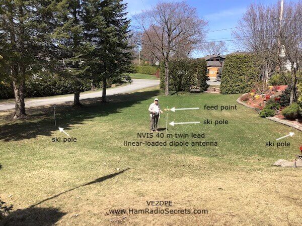
The 40 meter half-wave dipole antenna, intended for NVIS duty, described in the schematic diagram above, is made portable for field work by using linear-loading technique which will yield an antenna span about 33% shorter than normal! That's a very manageable 44 feet (13.4112 m) instead of 66 feet (20.1168 m) at 40 meters... and it's just as efficient as the full-size dipole version at the same height!
What's a linear-loaded dipole?
- The portable antenna, depicted above, is made with 300 ohms twin lead. You could use 450 ohm ladder line, but the twin lead is lighter and more manageable for easy portability for field work.
- The twin conductors, at the extremities of the antenna, are connected together.
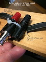
- Note the open gap in the center, above the feed point. The gap is essential.
Please note that, if you bridge the gap (above the antenna feed point), by connecting the upper twin lead conductors together, you will end up with a classic folded half-wave dipole which, being only 44 feet (13.4112 m) long, will resonate much higher that 7 MHz!
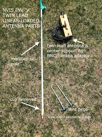
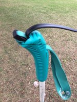
The dipole is installed horizontally, held about one meter (3-4 feet) above ground by three ski poles, one in the center and one at each end. It's low height is what makes this antenna only suitable for NVIS duty.
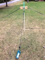
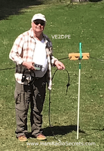
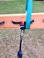
No DX possible with this antenna! You may hear some, during the better years of a sun-spot cycle, but they are not likely to hear you if you answer back!
The antenna is fed directly with RG8-X coax, using a UHF SO239 to BNC male adaptor, connecting to a BNC to dual banana adaptor at the dipole feed point.
Two ferrite RF chokes are installed about six inches from
each end of the coax to prevent common mode RF feedback from hampering
the action of antenna tuners and/or the transceiver itself.
My KX2's internal tuner had no trouble dealing with this antenna, mainly because it did not have to intervene! ;-) The FT891 does not have an internal tuner, yet it had no trouble working with the very low SWR of the antenna.
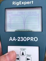
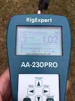
- The antenna resonates in the middle of the 40 meter band, at 7.150 MHz. The SWR there is 1.02 to 1. Neat!
- Its 2:1 SWR bandwidth stretches over 275 kHz, from 7.05 MHz to 7.280 MHz.
I was only using a one-meter length of 50 ohm coax when I ran my tests with a RigExpert AA-230PRO antenna analyzer.
WHAT IF... ?
A few ham radio operators wrote to ask: What happens if I only use one center support and drop the extremities of the NVIS dipole close to ground, to form an inverted 'V’?
That would mean two support poles less to carry when in the field!

Now, I must remind you that, ideally, a NVIS antenna should be horizontal to ensure vertical radiation for maximum local and near regional coverage. Nevertheless...
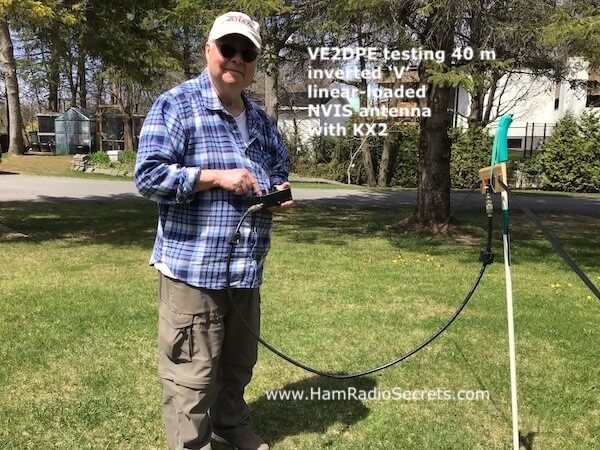
Here is what happened when the end support posts were removed and the dipole extremities were simply tied to tent pegs near the ground. The result was an inverted 'V' with the following characteristics:
- The resonant frequency dropped down to 6.59 MHz, below the 40-meter band.
- The SWR at that frequency rose to 1.6:1
However, I knew there was a way to make the same inverted 'V' antenna resonate back up into the 40-meter band. All I had to do was to make the antenna shorter... to make it resonate higher in frequency.
But I did not want to cut the twin lead extremities! Instead...
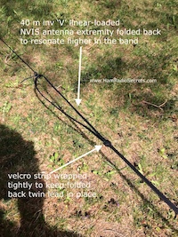
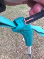
- I tried folding each extremity back on itself about six inches (15 cm). Sure enough, the resonant frequency went up, but not enough. It was still under 7 MHz.
- Then I tried again, but this time, folding back about 14 1/2 inches (17 cm) arbitrarily, no science there! I used small strips of Velcro, wrapped tightly around the overlapping twin lead, to hold the folded part of the twin lead in position.
(Remember, the twin leads at each end must remain connected together to maintain the integrity of the linear loading.)
Bingo!
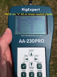
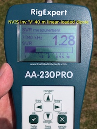
- The resonant frequency of the inverted 'V' NVIS antenna went up to land within the 40-meter band, at 7.04 MHz!
- The SWR at that frequency went down to a very manageable 1.28:1.
The advantage gained by folding back the twin lead in itself at each end of the antenna is that this technique makes the resonant frequency field-adjustable! You only have to:
- slide the folded portions (increase the overlap) of the twin lead at each extremity toward the dipole center to raise the frequency of resonance;
- or reduce the amount of overlap, at each end, to lower the frequency.
The other great outcome is that, as soon as I plugged the 40 m inverted 'V' NVIS antenna to my KX2, I dialed around and heard NE9EE on 7.0556 MHz from Fort Wayne Indiana calling CQ, coming in loud and clear (S5 to S6). That's roughly 1100 km (685 miles) away from my QTH (near Joliette, Québec)! (May 17, 2020, at around 15h30 UTC.)
Note also (in the video above) that the band went very quiet when he stopped transmitting! No
atmospheric noise or other electromagnetic interference, which is
exceptional for my area. That's a major advantage with the NVIS antenna.
Sadly,
I did not have a key plugged in! That would have made a great live demo
QSO with the NVIS inverted 'V'. Oh well. Next time.
Needless to say, I was very happy with the results anyway.
THE RESULT OF WHAT IF... ?
Tom, VE3YTN, activated a Parc on The Air (POTA) with it. He was impressed (his word) with the results. Read about it here.
We now have two NVIS antennas rolled into one.
- The original configuration: a horizontal (twin lead) linear-loaded NVIS dipole which requires one center support and two end supports to keep the dipole 3-4 feet (1 to 1,2 m) above ground, as described above.
- A second configuration: an inverted 'V' (twin lead) linear-loaded frequency adjustable NVIS dipole, with a greater angle than 90 degrees under the apex, which requires...
- only one center support to keep the apex about 4 feet (1,2 m) above ground
- and a tent peg with a piece of insulating string at each extremity.
The take-home lesson here is:
it pays to experiment!
So, there you are. These two versions of a portable linear-loaded NVIS antenna will make it easy for you to try your hand at NVIS communication on 40 meters.
73 de VE2DPE - Claude
P.S. I was motivated to experiment with NVIS communications after reading this article by Ben Witvliet, PhD, Radio Science Research Manager, Department of Electronic and Electrical Engineering Bath, United Kingdom.
73 de VE2DPE
Claude Jollet
104-30 avenue des Berges,
Notre-Dame-des-Prairies, Québec, Canada J6E 1M9
QTH Locator: FN36gb
Disclosure
If
you make a purchase via a link on this site, I may receive a small
commission on the transaction, at no extra cost to you. Thank you!
(One word queries work best)
HF Antennas
Section
Contents
VHF/UHF Antennas
FOUND THIS
SITE
USEFUL?
VE2DPE
Is a member
in good standing
of


Also a proud member of an international community of solopreneurs
using SoloBuildIt!
(SBI!)
to promote my self-published eBooks
since 2005.
See my review
of this unique product for online businesses.
CQ CQ CQ
If you have a question, a comment or a topic you would like me to cover, please do not hesitate to ask here.
