A Homebrew Antenna Tuner
Carefully Thought Out
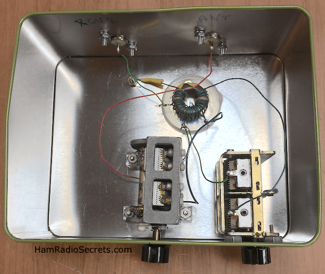
I decided to build a homebrew antenna tuner because I needed a passive pre-selector network to match an experimental end-fed wire antenna to my QS1R SDR receiver.
Please Note:
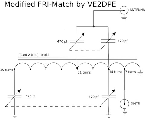
In the last version of my modified FRI-Match (diagram above), I replaced the 470 pf variable capacitors with 500 pf.
The QS1R SDR receiver probably does not need this much pampering to perform exceptionally well, but I was curious nonetheless. Below is the network design that I settled on for my first attempt.
My goal was to see if I could improve reception on the lower frequency amateur radio bands such as on 160 meters (1.8-2.0 MHz), 80 meters (3.5-4.0 MHz) and 40 meters (7.0 - 7.3 MHz).
Specifically, I was hoping that my homebrew antenna tuner would improve my signal to noise ratio on the aforementioned bands.
I also wanted the tuner to be easily reproducible. That meant:
- The least complex network.
- A low parts count.
- And sacrificing as little as possible in performance!
The Search
For The Best Of Breed
I studied the most popular antenna tuner networks in search of the best set of compromises for my purposes. I published a short summary of my preliminary findings on tuners in my ebook on HF antenna accessories (see ref.1 below). In summary:

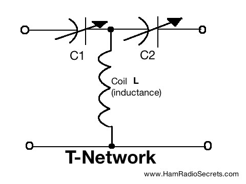
T-network: high parts count and inefficient (a.k.a. lossy), even if seemingly effective in matching a wide range of complex antenna system impedances.
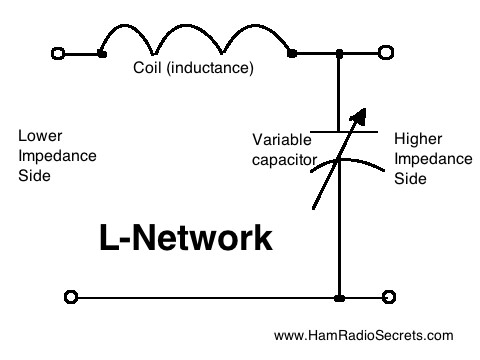
L-Network: much more efficient but often need large capacitance (hard to find and expensive) variable capacitors, especially for use at lower frequencies.
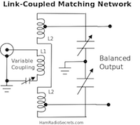
Link-coupled network: this is where things got interesting. While reading the many articles that were published on the Web and amateur radio books, I was discovering that they had a lower parts count and, in some instances, were less complex to build while remaining capable of transforming a fair range of impedances down/up to 50 ohms - which is the nominal input/output impedance of HF transceivers and amplifiers.
I learned that, much like L-networks, the efficiency of link-coupled networks was much greater than the popular T-networks. The drawback was that their higher "Q" meant that one could not deal with as large a range of antenna system impedances and operating frequencies as one can with a T-network.
That did not deter me. I intended to design my homebrew antenna tuner to suit my specific antenna system situation, instead of using a more "universal" design which is a "one-size-fits-all" device normally intended to be useful in "most" circumstances, but generally only with reasonably well-designed HF antennas.
Furthermore, I wanted the tuner to help me experiment with my many oddball home-brewed HF antennas!
The Z-Match Network
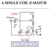
While browsing around for QRP tuners, the Z-Match caught my attention. The Z-match network was originally described by R. W. Johnson, W6MUR in the July 1954 edition of the QST magazine published by the ARRL.
It met my requirements stated above and it was a proven tuner network.
I found that some amateur radio operators had since experimented with variations of the original design that had inspired the Z-Match.
I finally stumbled on a very interesting modified design by Frits Geerligs PAØFRI (Ref-2). He named it: FRI-Match.
The FRI-Match
for
A Homebrew Antenna Tuner
Instead of using link coupling to the antenna, his design uses capacitive coupling to the main coil. I was immediately intrigued.
The parts count of this idea was as low as it could get:
- Two dual-section air variable capacitors - 470 pf per section.
- One inductance - a coil with taps on an iron powder toroid.
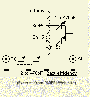
No switches! Just two knobs to play with. Nice and simple.
That's where I decided that my first homebrew antenna tuner project was going to be based on PA0FRI's design.
My Experimental Version
I modified PA0FRI's design which is itself a modified version of the Z-Match. He had found by experimentation that an inductance somewhere between 5-8 µH was suitable to match antennas on frequencies ranging from 3.5 MHz (80 meter band) to as high as 28-29.7 MHz (10 meter band).
Please Note:
In the last version of my modified FRI-Match (diagram above), I replaced the 470 pf variable capacitors with 500 pf.
However, since I intend to use my homebrew antenna tuner on the lower frequency bands (160M to 40M) I arbitrarily chose a maximum inductance of around 17-20 µH - assuming that more inductance would allow me to use variable capacitors having only a maximum of 470 pf per section on the lower ham radio bands.

Therefore, based on Amidon's tech notes on its iron powder toroids, I wound 35 turns of #22 AWG insulated wire (extracted from telephone cable) on a T106-2 (red) toroid core that I had on hand. I made taps at 7, 14 and 21 turns from the grounded end. By the way, the "2" material of the toroid is suitable for use on frequencies ranging from 2-30 MHz.
Here are technical references from Amidon Corp. that will prove helpful in calculating the number of turns for the inductance values that you will want to experiment with:
Amidon Corp. Iron Powder - to calculate # turns for specific inductance
https://www.amidoncorp.com/product_images/specifications/1-02.pdf
Amidon Corp. Iron Powder Specifications
https://www.amidoncorp.com/product_images/specifications/1-05.pdf
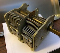
Next I had to find two dual-section air variable capacitors. I rummaged through my junk box(es) but only found two old units that I had extracted from superhet receivers some decades ago. They did not have the amount of capacitance that I needed for my project.
After browsing around the Web for a few hours, I found what I was looking for at Peebles Originals (Ref-3): two dual-gang variable capacitors (approximately 500 pf per section).
A Tuning Indicator
Since my homebrew antenna tuner was meant to be used primarily in receive mode, with an experimental end-fed antenna, I intended to use my trusted antenna analyzer to help me find preliminary capacitor settings on each band below 15 MHz.
Of course, as most of you will also want to use your tuner in transmit mode, I am including information to incorporate a SWR indicator for QRP power levels in the tuner.
QRP SWR Meter
There are many possible SWR meter circuits. You could opt for a simple led tuning indicator. You will find a suitable design on PD7MAA's website (Ref-4).
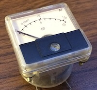
But, if you're like me, you love analog dials.
I happen to have this nice one in my junk box.
There is a very nice resistive SWR bridge design by Ian G3ROO and Tony G4WIF that you might want to try (Ref-5). I find that design particularly clever because it protects the QRP final amplifier from SWR greater than 3:1. It is definitely worth consideration. I intend to try it and I will let you know what I think.
You will also find many documented variations of the classic SWR meter on the Web. For example, you might find EA4NZ's Web page informative (Ref-6).
Experimental Results
My homebrew antenna tuner is capable of handling 100 watts if I need to use it with my IC-7200 XCVR. I will publish the results of my experimental tuner on this page as I progress through variations of it. If you want to be alerted when that happens, I suggest that you subscribe to my blog's RSS feed.
The Ham Radio
Transmatch
Explained
 The MFJ Versatuner II
The transmatch, or ham radio antenna tuner, is a variable impedance matching device. It is used between the transmission line of an HF antenna system and a transceiver or transmitter.
Its purpose is to make the antenna system "look like" a purely resistive load - usually 50 Ohms for the vast majority of ham radio transceivers or receivers nowadays.
The ham radio operator varies the inductance, along with input and/or output capacitance, in an effort to "tune out" (cancel out) the capacitive and/or inductive reactance that may appear at the transmitter end of the transmission line.
Why match the antenna system impedance to the transmitter's output impedance?
Because maximum transmitted energy is transfered to the load when the load matches the characteristic impedance of the transmitter output (usually 50 Ohms).
That is what we all want ... that all the RF energy generated by the transmitter reaches the antenna, instead of heating the components of the final amplifying stage and risk damaging them.
Please note that the transmatch - in this case your homebrew antenna tuner - when installed between the transmitter output and the transmission line . . .
- will not eliminate the standing waves that may appear on the transmission line;
- will not eliminate the loss of signal within the transmission line due to standing waves;
- will not tune the antenna to resonance, at the other end of the transmission line (an unfortunate popular misconception).
T-Networks VS L-Networks
Be aware that... T-network antenna system tuners are the least efficient of all possible network configurations.
Most inexpensive "antenna tuners" out there today are T-networks. The MFJ-940D pictured above is an example.
Why do manufacturers offer them? Because they do not cost much to manufacture ... and, consequently, cost less to buy.
For the same reasons, this is usually the tuner network configuration that ham radio experimenters choose for their homebrew antenna tuner project.
The High-pass T-network
Mind you ... the T-network configuration will do the job of transforming complex antenna system impedance, appearing at its output (antenna system side), to a 50 Ohm impedance at its input (transmitter side).
At least some RF power will get through the T-network and make its way to the antenna.
Where things get prohibitive is when you are operating under less than ideal HF propagation conditions. You will often not hear stations that you would normally be able to copy with L-network tuners. L-networks are much more efficient.
In the process of cancelling out unwanted antenna system reactances, the T-network will waste a prohibitive portion of the RF energy as heat! (ref: ARRL Antenna Handbook, chap.25).
The RF loss on transmit may not prevent your signal from being heard, somehow, when propagation conditions are favorable but, on receive, the loss of RF energy is often catastrophic!
That's why I chose to modify the FRI-Match (above) for my homebrew antenna tuner project.
L-Network Transmatch
 LDG AT-600 Pro
L-networks require very large capacitance values ... in the thousands of picofarads (pf) at low frequencies! Variable capacitors with this much capacitance are rare and extremely expensive.
That is the main reason why L-networks are rarely chosen for a homebrew antenna tuner project.
The AT-600Pro Autotuner by LDG neatly solved the problem of cost while preserving full flexibility, efficiency and effectiveness of the L-network configuration! :-)
The AT-600 automatically chooses the proper L-network configuration, to adapt itself to high or low impedance situations, and switches fixed values of capacitance in or out to fine tune for a match.
Very clever! That's why I chose the AT-600Pro transmatch instead of the MFJ 940D for multiband operation with my Carolina Windom antenna.
I modified the 940D for 160 meter work by adding fixed capacitors in parallel with the input and output variable capacitors. It's a compromise but it lets me go on 160 with a second, homemade antenna that I also use as receive antenna for my QS1R SDR receiver.
References
- HF Antenna Accessories: Chapter Two - The Antenna Tuner. Essential knowledge to build a homebrew antenna tuner successfully.
- Frits Geerligs PAØFRI FRI-Match
- Peebles Originals Vintage Radio Kits and Parts
- LED Tuning Indicator for QRP by PD7MAA
- Resistive SWR Bridge for QRP (PDF)
- HF SWR Meter Schematics
- Amateur Radio HF Antennas (ebooks by VE2DPE)
Here is what the ARRL has to say about antenna tuners.
73 de VE2DPE
Claude Jollet
104-30 avenue des Berges,
Notre-Dame-des-Prairies, Québec, Canada J6E 1M9
QTH Locator: FN36gb
Disclosure
If
you make a purchase via a link on this site, I may receive a small
commission on the transaction, at no extra cost to you. Thank you!
(One word queries work best)
HF Antennas
Section
Contents
VHF/UHF Antennas
FOUND THIS
SITE
USEFUL?
VE2DPE
Is a member
in good standing
of

Also a proud member of an international community of solopreneurs
using SoloBuildIt!
(SBI!)
to promote my self-published eBooks
since 2005.
See my review
of this unique product for online businesses.
CQ CQ CQ
If you have a question, a comment or a topic you would like me to cover, please do not hesitate to ask here.
