A Simple Low-cost
HF Preselector
I needed an HF preselector to improve my SDR general-purpose receiver's reception of ham radio HF bands. It's a direct conversion receiver. It has no preamplifier nor preselector circuitry.
Here is the circuit diagram. I'll explain both the theory and construction in detail below.
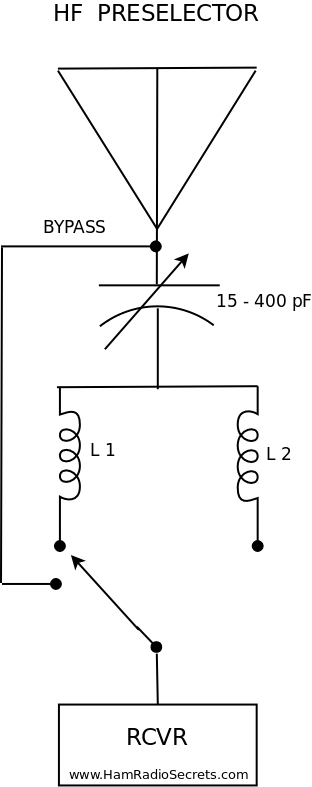 A larger image of the HF preselector follows below.
I did not want to bother with a preamplifier. I wanted to keep things simple and easily reproducible.
Granted, I could get some sort of pre-selection done by the antenna. But that would mean one antenna per ham band! I did consider doing just that, at first. But the project died an early death when I started making plans to build wire antennas for each HF band - 160 meters to 10 meters!
I have the space ... but not the desire to go to all that trouble.
As I already use a random length end-fed inverted "L" wire antenna - actually it's 135 feet long - I turned to the passive pre-selector solution.
I'll spare you the theory and calculations, for now (more on this below). Suffice to say that - after having checked my stock of spare parts - I found that I had all I needed to build a preselector that would (in theory) do the job of improving reception on each of the HF bands.
In fact, I was mostly interested in improving things on the lower frequency bands 160 meters, 80 meters, 60 meters and 40 meters. I ended up building two LC series circuits in a tin metal box that my wife graciously agreed to part with ... pending future considerations, of course. Nothing comes free in this world except, of course, the information I am sharing with you here.
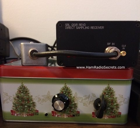
This is what the finished, fully functional prototype looks
like. It's the box with the Xmas trees on it! One knob for the variable
capacitor. One knob for the switch that selects which inductance to put in-circuit - thus selecting the ham bands that will be enhanced.
I'll improve the looks for the next version by reducing the size of the enclosure and paint it black ... when I find the time ;)
Right now, it works as is. It improves reception by adding one or two dB gain on all HF bands except 10 meters.
That's good enough for me, for now. I will experiment with modifications to get the preselector to improve things on ten meters also. The minimum capacity of my variable air capacitor appears to be too high to let me reach up to 28-29.7 MHz. I may also have too much inductance in play for the variable capacitor that I have.
- I can either switch in extra capacitance in series to reduce the unknown minimum capacitance of my variable capacitor.
- Or, I can add a more appropriate inductance (less than 1 µh) and retain the same air variable capacitor - to gain access to ten meters and perhaps 6 meters as well.
These modifications will be for version 2, when I get the time. Right now, with the solar cycle being at it's minimum, there is not enough action on ten meters to warrant the mods (effort).
I have, as always, other projects in the works - one of which is writing accounts of my experiments on this web site (wink).
Building The
HF Preselector
I always keep a selection of powdered iron toroids and different gauges of enamel wire in stock. I'm always experimenting and testing ideas and I hate having to order parts online because it delays my experiments.
The Toroid Inductors
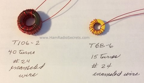
The T106-2 (red) toroid is L1 in the schematic diagram. The T68-6 (yellow) toroid is L2.
I used the enamel wire that I had on hand. The 24 gauge wire happened to allow me to nicely fit 40 turns on the T106 core (L1).
I could have used larger size wire for the few turns required to get the required inductance for the higher bands on the smaller T68 toroid (L2) ... but I did not have any! The wider spacing between the turns is not ideal according to Amidon's tecnical documentation.
Using the technical documentation from Amidon Corp. for its iron powder toroids, and the equations for resonant circuits (see the section on theory below) - I came up with the following aproximations:
- I calculated that a 22 µH inductor (L1) would be allow me to use my variable capacitor for the lower frequency bands (160-40 meters).
- I also determined that a 1 µH inductor (L2) would (in theory) allow me to obtain resonance on the 30 meter to 10 meter bands.
As it turns out, I am not able to obtain resonance on ten meters! That's likely due to stray capacitance and/or too much inductance in L2 (coil winding not up to par - I should have used larger wire ;).
Here is the technical documentation from Amidon Corp. that I had to refer to when building the toroidal inductors for my HF preselector project.
- Iron powder material and usage:
http://www.amidoncorp.com/product_images/specifications/1-03.pdf
- Iron Powder Toroidal Cores for resonant circuits:
6 material: http://www.amidoncorp.com/product_images/specifications/1-06.pdf
2 material: http://www.amidoncorp.com/product_images/specifications/1-05.pdf
- Iron powder material vs frequency range:
http://www.amidoncorp.com/product_images/specifications/1-08.pdf
- Inductance values of iron powder toroidal cores as a function of material mix and core size:
http://www.amidoncorp.com/product_images/specifications/1-09.pdf
- Formula to calculate (desired) inductance:
http://www.amidoncorp.com/product_images/specifications/1-02.pdf
- Iron powder core size vs number of turns and wire size:
http://www.amidoncorp.com/product_images/specifications/1-10.pdf
The Air Variable Capacitor
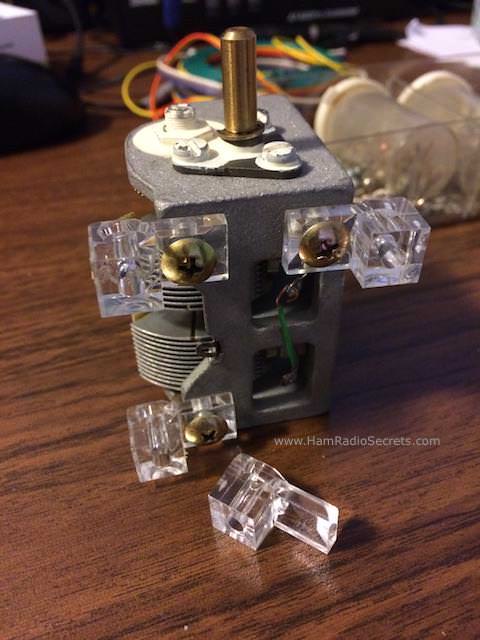
This is the air variable capacitor that I chose to use for the HF preselector project. I had a few others in stock. All were used units that I had either salvaged from old gear years ago - or bought online.
This one has a capacitance range of approximately 15 - 410 pF.
You will have noticed - in the circuit diagram above - that the variable capacitor must float above ground potential.
Therefore, I rigged it so that I could install it firmly to the bottom of the enclosure, with none of it's parts touching the enclosure (which is at ground potential via the coax braid to the receiver). To that end, I used plastic angle brackets - which are normally used to secure a mirror to a wall - as insulating feet for the variable capacitor.
Note also that I punched a big enough hole in the front of the cabinet so that the variable capacitor shaft would not come in contact with the metal enclosure.
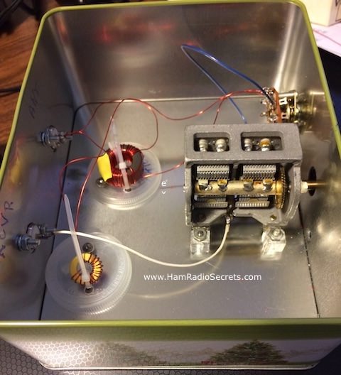
Overhead View of the HF Preselector
I used plastic pill bottle caps under the toroidal inductors to insulate them from the chassis. The toroids are held in place on the caps with small tie-wraps.
I used a 5/8in. (Greelee type) round sheet metal knockout punch for the SO-239 holes on the back wall - and for the variable capacitor shaft.
I drilled a 3/8 in. hole for the rotary switch.
The Theory Behind
The HF Preselector
This is the basic circuit diagram of my HF preselector. This simple circuit - composed of a coil in series with an air variable capacitor - becomes resonant at a certain frequency when the absolute reactance value of the capacitor |Xc| is equal to the absolute reactance value of the inductor |XL|.
The capacitive reactance is negative while the inductive reactance is positive. When they are equal in absoluta value, they cancel each other.
|Xc| = |XL|
In other words:
2 π f L = 1 / (2 π f C) at resonance
where:
f = frequency in Hz
L = inductance in H
C = capacitance in F
At resonance an extremely narrow band of frequencies are thus allowed to pass through the HF preselector tuned circuit almost unimpeded. The small resistance in the coil winding will be the only cause of attenuation of the RF signal. But it will be negligible at HF frequencies.
Impedance rises sharply on either side of the resonant frequency, rapidly preventing other frequencies to pass through to the receiver.
Solving the equation above for f enables us to find the resonant frequency for any combination of inductance and capacitance.
f = 10³ / (2 (√ LC))
Where:
f = frequency in MHz
L = inductance in µH
C = capacitance in pF
When L is known you can find the value of C at the given frequency of resonance
25330 / (f² * L) = C
When C is known you can find the value of L at the given frequency of resonance
25330 / (f² * C) = L
For example:
At 7MHz, if L is known:
If L is 5 µH
C = 25330 / (7² * 5) = 103,4 pF
If L is 2 µH
C = 25330 / (7² * 2) = 258,5 pF
At 7 MHz, if C is known:
If C is 30 pF
L = 25330 / (7² * 30) = 17,2 µH
If C is 300 pF
L = 25330 / (7² * 300) = 1,7 µH
Conclusion
I had fun researching and building this simple HF preselector. I hope you will too.
73 de VE2DPE
Claude Jollet
104-30 avenue des Berges,
Notre-Dame-des-Prairies, Québec, Canada J6E 1M9
QTH Locator: FN36gb
Disclosure
If
you make a purchase via a link on this site, I may receive a small
commission on the transaction, at no extra cost to you. Thank you!
(One word queries work best)
EQUIPMENT
Section
Contents
FOUND THIS
SITE
USEFUL?
VE2DPE
Is a member
in good standing
of

Also a proud member of an international community of solopreneurs
using SoloBuildIt!
(SBI!)
to promote my self-published eBooks
since 2005.
See my review
of this unique product for online businesses.
CQ CQ CQ
If you have a question, a comment or a topic you would like me to cover, please do not hesitate to ask here.
