Improving an Attic Shortwave Antenna - A Case Study
A shortwave listener, using an attic shortwave antenna, wrote HamRadioSecrets.com asking for suggestions on how to improve his reception. The description he gave of his installation revealed several shortcomings that could easily be remedied by:
- eliminating the sources of signal loss;
- removing a potential source of parasitic interference;
- implementing signal enhancing measures.
You can refer to his request in the Antenna Forum here. Luckily, his attic and the shake shingle covered roof are entirely made of wood, with no metal objects to contend with anywhere. All told, a friendly environment for an indoor SWL antenna.
His shortwave receiver is a Yaesu FRG-8800.
Here are the possible solutions for each shortcoming that his attic shortwave antenna installation presents, along with the recommendations I made to him.
The First Problem to Solve:
Poor Insulation of
the Attic Shortwave Antenna Wire
This is the most important aspect to improve. Bare copper antenna wire stapled directly on wood rafters causes loss of RF signal energy. With time, bare copper oxidizes.The wood, where the wire is tightly stapled to, absorbs some of this oxidization and forms a loose yet lossy bond with the wire. The staples themselves dig into the wood and further increase the bond.
RF energy is lost at every stapled point. These losses add up. They may not be very apparent when signals are strong. But when signal strengths are marginal or very weak ... their faint energy, captured by the antenna, is lost in the stapled points.
The Solution
The most economical and highly recommended measure is to insulate the bare antenna wire.
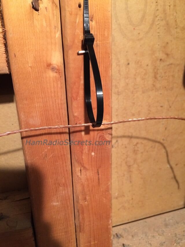
Remove staples. Instead, staple a closed tie wrap (forming a loop) at each stapling point. Run the wire through the loops and let it hang slightly away from the wooden rafters. Insulate the wire with electrical insulating tape where the bare wire might come in contact with wood or any other foreign object.
Or ... replace the oxidized bare copper wire with insulated copper wire. Then, run the wire through tie wrap loops as above, slightly away from the rafters.
The Second Problem to Solve:
Coax Shield Picking Up Interference
The coax shield, when not terminated at each end, acts as an independent antenna. It can potentially capture and contaminate the "valid" RF energy - coming in from your attic shortwave antenna - with undesirable electromagnetic and electrostatic interference. This interference is not being dissipated into a proper load because the coax shield is not terminated at both ends!
As a result, the unwanted interference causes the background noise to increase in the receiver, thus reducing the signal to noise ratio. Signals coming in from the antenna need to be stronger to overcome this extra unwanted noise!
Solution
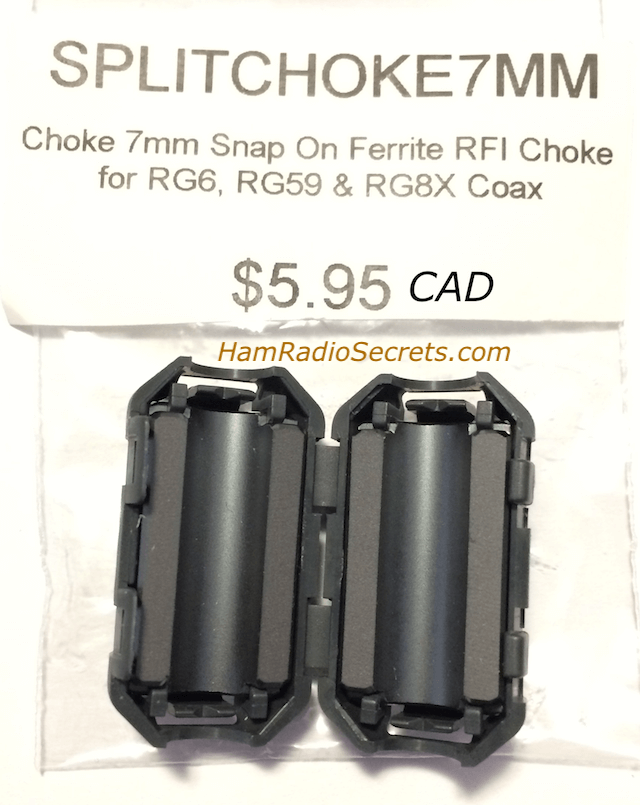
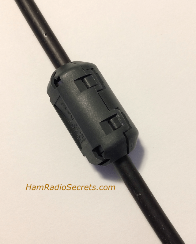
Option One: A stopgap measure would be to install at least two ferrite RF chokes on the existing coax (with the "floating" shield); one RF choke, half way down from the antenna; the other, a foot or two away from the receiver. It might prove to be enough to prevent the floating coax shield from acting as an antenna. On the other hand, you will never know if you are shortchanging yourself.
Option Two: Another stopgap measure would be to replace the coax with a length of insulated copper wire, connected to the Hi-Z terminal on the back panel of the FRG-8800.
That would make your end-fed antenna 150 feet long which is not a problem in itself.
- You would eliminate a source of unwanted interference: the "floating coax shield".
- But you will introduce another potential source of interference. The near vertical portion of wire (20 ft) from the attic shortwave antenna to the receiver could pick up vertically polarized electrostatic interference!
Option Three: the one I recommend.
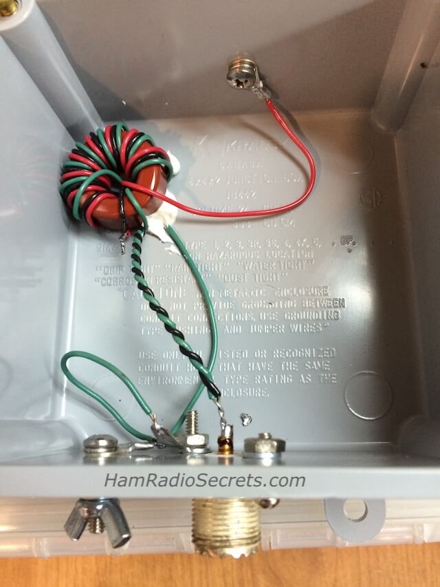
Install a 9:1 UNUN at the antenna end of the coax. (UNUN stands for unbalanced coaxial line to unbalanced antenna). You should then make the coax shield connect properly to the PL-259 connectors at each end.
The coax shield would then be properly terminated at both ends and stop being a "rogue antenna”.
- You could opt for a commercially made 9:1 UNUN
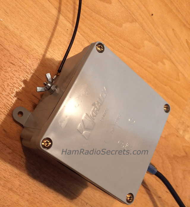
- or build a homemade one like I did. I used an electrical plastic box made for outdoor use.
Third Problem to Solve:
Impedance Mismatch
An impedance mismatch between:
- the usually high and complex impedance of an end-fed antenna system appearing at the receiver end of the coax,
- and the receiver's low impedance (50 ohms) at the SO-239 coaxial connector,
. . . causes inefficient transfer of the scant RF energy coming in from the antenna to the receiver.
Solution
Install an L-network impedance matching device (tuner) between the coax and the receiver. Thus, you will be able to improve reception as you manually tune it to transform your attic shortwave antenna system impedance to match your receiver's input impedance.
By the way, by antenna system, I refer to the combined ensemble of:
- the antenna;
- the coaxial feed line;
- the impedance transforming (matching) device.
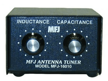
A good example of such a device is the MFJ-16010 L-Network Random wire tuner. A L-network is the best impedance transforming configuration for end-fed antennas. (Stay away from lossy T-network configurations).
Fourth Problem to Solve:
The Lack of a Good RF Ground
You could try a counterpoise. This is a length of wire that is added to simulate the presence of a good RF ground right at the receiver - when no good ground is available (like a water pipe) which is generally the case for those who live in an apartment building.
Normally, a passive counterpoise is a quarter wavelength of insulated copper wire connected, in your case, to the receiver's ground post. The counterpoise wire can simply lie on the floor, along the baseboards. That could certainly help a little ... but for one band only!
Admittedly, it would not be a very practical to have a quarter wavelength of wire for each amateur radio band you would like to listen to, not to mention other HF bands!
Please note that I have not tested the tuned counterpoise solution that follows.
But it certainly makes sense, in theory.
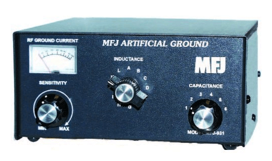
The MFJ-931 could potentially be used a tuned counterpoise for your attic shortwave antenna. Even
if it is mostly used by ham radio operators to solve problems while
transmitting, the MFJ-931 should also work for a receive-only purpose.
For best results, you would first tune the receiver to the frequency you
want to listen to. Pick a quiet spot on the band. You just want to
sample the background noise on the band at this time. As you would not
be transmitting, you would not be using the ammeter to tune the unit.
Instead, you would use your receiver's audio output and its s-meter as
indicators.
Then, you would tune the MFJ-931 for maximum noise or maximum s-meter reading.
The
MFJ-931 manual indicates that you should use a quarter wave
counterpoise wire for the frequency you want to listen to! We are back
with the "too many" counterpoise wires which is not practical.
You could try a single length of wire, 27-30 ft long, as a “general purpose" counterpoise. After all, the MFJ-931 enables you to tune it. It might work with only one length of counterpoise. *** Note: Again, I have not tested this solution.
Resist Temptations
HF Preselector
Some people may suggest inserting an HF Preselector between the antenna coaxial cable and your receiver.
A preselector is just a passband filter. It attenuates out of band signals at the expense of introducing an inband signal loss of 2 dB or more!
A passband filter would be of no use to you because the FRG-8800 has its own effective passband filters.
HF Preamplifier
Others might suggest inserting an HF Preamplifier between the coaxial cable, coming down from your attic shortwave antenna, and your receiver.
Preamplifiers are usually broadband. They amplify signals . . . as well as the atmospheric noise! The signal to noise ratio is not improved! It just forces you to turn down the volume.
To make matters worse, RF amplifiers generate and add their own noise to the mix!
But more importantly, amplified signals can easily overload the sensitive front-end amplifier in the FRG-8800, causing distortion. A preamplifier would be a counterproductive solution in your case.
In Short
Eliminate signal losses due to poor antenna insulation, solve the "floating coax shield rogue antenna" problem and implement signal enhancing measures. That should do it. You will have done all that is required to bring your antenna installation up to standards.
A Reminder
There are often times when no RF energy at all will reach your attic shortwave antenna during a solar sunspot cycle minimum.
But, at least, your improved antenna system will deliver more microvolts of RF when signals do manage to reach it! It will also catch more of the weaker signals from now on.
73 de VE2DPE
Claude Jollet
104-30 avenue des Berges,
Notre-Dame-des-Prairies, Québec, Canada J6E 1M9
QTH Locator: FN36gb
Disclosure
If
you make a purchase via a link on this site, I may receive a small
commission on the transaction, at no extra cost to you. Thank you!
(One word queries work best)
HF Antennas
Section
Contents
VHF/UHF Antennas
FOUND THIS
SITE
USEFUL?
VE2DPE
Is a member
in good standing
of


Also a proud member of an international community of solopreneurs
using SoloBuildIt!
(SBI!)
to promote my self-published eBooks
since 2005.
See my review
of this unique product for online businesses.
CQ CQ CQ
If you have a question, a comment or a topic you would like me to cover, please do not hesitate to ask here.
